


🚀 Drive Innovation Forward with Power and Precision!
The DROK DC Motor Driver L298 Dual H Bridge is a compact, high-performance motor controller designed for professional-grade projects. It supports a wide input voltage range of 6.5V to 27V, delivers a robust 7A output current per motor port, and can handle up to 160W total power. Featuring dual H-bridge architecture, it independently controls two DC motors with forward and reverse rotation capabilities. PWM input enables precise speed regulation up to 10kHz, while built-in under voltage protection ensures durability and reliability. Ideal for millennial professionals seeking efficient, versatile motor control solutions in compact form.


| ASIN | B06XGD5SCB |
| Batteries required | No |
| Best Sellers Rank | 201,570 in Business, Industry & Science ( See Top 100 in Business, Industry & Science ) 1,054 in Motor Speed Controllers |
| Customer Reviews | 4.4 4.4 out of 5 stars (185) |
| Date First Available | 7 Mar. 2017 |
| Item model number | 200206_OZ |
| Manufacturer | DROK |
| Product Dimensions | 5.5 x 5.5 x 1.6 cm; 41 g |
| UPC | 701822755689 |
C**L
Je mets l'accent sur la puissance de sortie car celle proposée par exemple par les modules L298 limitent la sortie à 2A alors que là avec 7A on fait face à la plupart des applications. Pilotage indépendant de 2 moteurs dans les 2 sens avec entrées PWM pour la variation de vitesse. Je l'emploie avec un Arduino UNO. Le variation de vitesse va de 0 à 100% (je dis bien 100% plus de découpage mais tension maximale). Pour la sécurité en cas de coupure d'alimentation alors que les moteurs sont à pleine vitesse le fabriquant conseille l'utilisation d'un relais pour protéger le dispositif de l'effet dynamo des moteurs qui induirait des tensions inverses sur les transistors à effet de champs (puisque plus alimenté par la coupure d'alimentation), moi j'ai mis un pont redresseur sur le moteur (entrées alternatives sur les bornes du moteur, la sortie plus vers le plus de l'alimentation et la sortie moins vers ... le moins (vous l'aurez deviné). La tension inverse reçue par les transistors est au maximum de 0,6V ce qu'ils supportent sans problème.
J**.
These are really nice motor controllers. Please be aware 5v input is NOT 5v input. It needs to match the high level logic voltage. If you are running a 3v3 microcontroller, supply 3v3 to this pin. If you supply 5v to that pin and run a 3v3 microcontroller, nothing will happen and the board will appear broken.
G**N
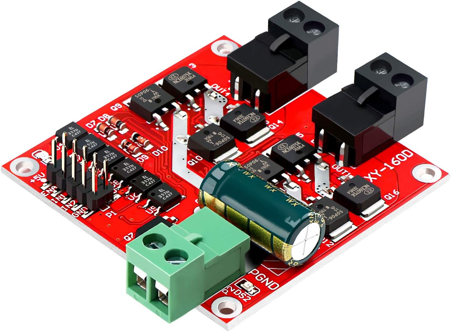
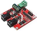
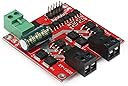
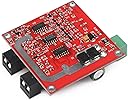
This unit is perfect for my application with a couple of 2-3 amp DC motors and worth far more than the cost. I require frequent direction changes and large starting current spikes, but the board stays cool and doesn't need heat sinks. The connectors have screw terminals and removable snap lock connectors which are excellent. The documentation looks great on glossy paper but needs some clarification. Here's a few tips and a Arduino test setup: 1) This double H-bridge can run two motors independently of each other. 2) Each motor can run forward, reverse, brake, full speed forward, and full speed reverse. 3) Categories of inputs (you provide these) to the board are: a) Main power (up to 15 amps) that is used to drive both motors. Read the instructions around voltages, current, peak current, fuses, etc... b) Control logic for Motor A c) Control logic for Motor B d) 5v power you provide into the board for it's logic processing, etc.. with very little current draw. 4) For the main power input, you need a capable power supply. I'm using a 10amp battery charger. 5) You must feed 5v into the board. The board has 5v (and ground) pins for each motor, but you only need to provide 5v and ground on one set of pins. 6) Each motor needs three 5v logic inputs. For motor #1 they are labeled IN1, IN2, and ENA1. 7) The two pins labeled IN1 and IN2 are fed from any two GPIO(Arduino) pins with HIGH or LOW to control the mode of the motor such as forward, reverse and brake. See the control logic table in the instructions. 8) The pin labeled ENA1 REQUIRES!!! a PWM output from Arudino. You MUST NOT apply a steady voltage from something like a potentiometer or DAC output. 9) Here's a basic test setup for Arduino UNO if you need it: Connect 5v and ground to H-bridge, Connect main power Connect motor(s), you just need motor A for this test Connect Ardunio pin2 -> H-bridge pin IN1 Connect Ardunio pin3 -> H-bridge pin ENA Connect Ardunio pin4 -> H-bridge pin IN2 Create a test sketch as follows: void setup() { pinMode(2, OUTPUT); pinMode(3, OUTPUT); pinMode(4, OUTPUT); } void loop() { digitalWrite(2, LOW); //forward digitalWrite(4, HIGH); //forward analogWrite(3, 178); //pin 3 is PWM, 178/255 = (about) 70% speed. Max is 255. delay(1500); digitalWrite(2, HIGH); //reverse digitalWrite(4, LOW); //reverse analogWrite(3, 76); //pin 3 is PWM, 76/255 = (about) 30% speed. Max is 255. delay(3000); } Hope this helps get you started.
A**I
Worked as described!
H**K
I am completely re-writing my review on this thing. I am using a Raspberry Pi 3 to drive the board. Here are some points to consider when using this board: 1. I applied 5V and a ground from my PI3 to the boards control pins per the instructions. This activates the power light for the control pins and sets all the control pins to just under 5V or HIGH. At first, this was not clear but after I figured it out, I could then adjust my programming to work with it. 2. I can activate Motor 1, perfectly. I can activate motor 2 perfectly. I have a major issue of activating both at the same time. If I try this, the boards seems to get confused on which one it is driving. To test this problem, I set a 1000ms delay between starting the first and second motors. They both turned on and ran for the allotted time frame of 5000ms. It seems that board needs a delay between turning on the separate outputs. In addition, the more the resistance on the motors, the longer this delay needs to be. In other words, if I put the chassis on a stand, the delay needs to be about 500ms. If I put the chassis on the ground with the wheels touching the ground, it has to be well over 1000ms delay. My conclusion is that there is interference or confusion in the board when performing both tasks at the same time. I am going to try to power the controller with a Arduino Uno and see if this makes a difference. It could be that this board is not meant to work with a PI3. I will post my results here for future buyers to understand this product more as the instructions are not very useful at all and the companies website is horrible and does not even mention this product in anyway. Update: I was able to figure out the issue with this board. Using the Arduino, I wrote code first enable the motors at full speed. I had the same jumpy result as with the PI3. I then switch to PWM and it works perfectly. FINALLY. Apparently this board only can handle a slow increase in speed when handling more than one motor at the same time. Either way, product does not do what is says so I cam keeping with 2 stars.
Trustpilot
1 day ago
1 month ago